The city of San Miguel de Ibarra, generally known as Ibarra, in the Republic of Ecuador, is situated about 115 km north of Quito, in the valley that crosses the River Tahuando, southwest of the Yahuarcocha lagoon.
The Decentralised Autonomous Municipal Government of Ibarra Canton, with the support of the International Bank for Reconstruction and Development (IBRD), implemented the “Improving transport infrastructure in Ibarra” project. This includes the city´s Ring Road project, the northern section of which has already been built, except for the crossing over the River Tahuando and the remaining southern section.
The River Tahuando sharply divides the municipality in two, so the Pan-American highway, which in this section connects Ecuador with Colombia, has only one connection access, that of the Los Molinos bridge.
TYPSA was chosen to carry out the evaluation of alternatives for the connection between the northern section of the ring and the access to the Yahuarcocha lagoon, the optimisation of the route of the southern section, and the definitive engineering, social and environmental studies for the selected alternative, as well as the definitive route of the southern section of the ring road.
The project involves a series of improvements for transport and mobility in the town: avoiding the passage of long-distance vehicles through the urban centre, improving connections between parishes, facilitating access to the road network, providing adequate road infrastructure to the different production areas and overcoming natural barriers, such as the River Tahuando. The benefits include increasing safety and comfort, reducing air pollution, and improving service level, with the consequent savings in the operating costs of vehicles and in the travel time of users.
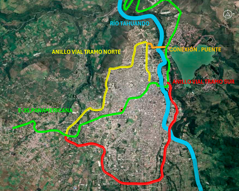
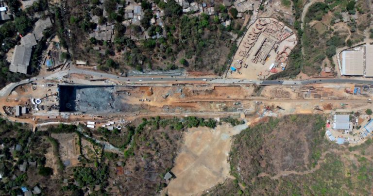
The southern section of the Ring Road is a high-capacity 12.5 km urban road, on which 9 bridges have been designed over different rivers, together with an underpass, 22 transverse drainage works, and 16 roundabout-type intersections and T-intersections.
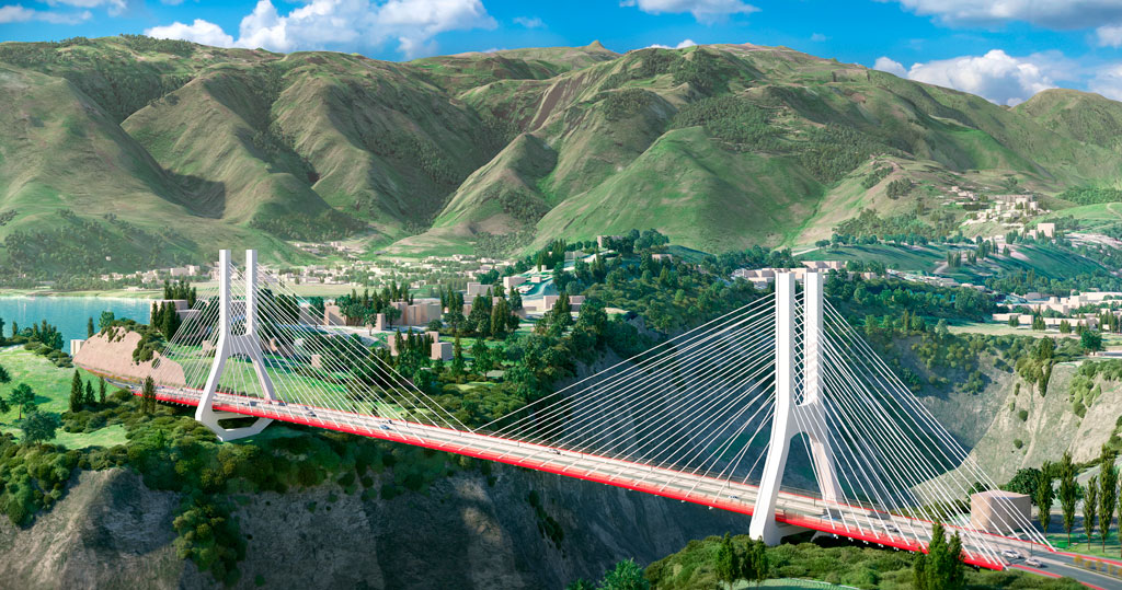
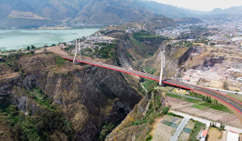
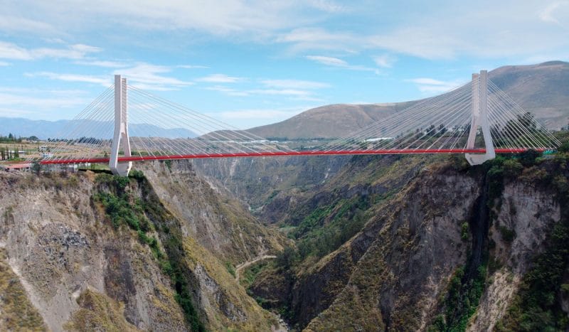
The most significant element of the bypass is a 1,190 m long high-capacity road connecting the northern section, crossing the River Tahuando by means of a 430 m cable-stayed bridge over the 180 m deep gorge through which the river runs.

Structural diagram of the bridge
The main 290 m span makes it possible to cross the formidable ravine with some protection for the foundations of the pylons, the position of which is conditioned on the western side by the built-up urban area, which curves with a 90 m radius, just before the alignment of the bridge, and on the eastern side due to the slope entering a steep cut, reducing the maximum lateral spans to 70 m. The deck has a width of 26.3 m.
The typical design of a three-span cable-stayed bridge would require larger lateral spans to balance the 290 m central span, and for this reason the longitudinal layout of the bridge is not canonical, achieving balance with a heavier deck section in the lateral spans, also known as restraint spans. In the central part, the deck is very light, with a double post-tensioned concrete box girder longitudinally. Between the girders, pre-tensioned beams and a continuous slab form the deck surface. In the retained spans, the deck is made with a lightened slab. To further balance the weight of the central span, inverted supports are necessary on the pylons.
Seismic strategy
Lead-core bearings provide seismic isolation for the bridge, absorbing earthquakes that exceed the frequent rate (T=225 years) but remain below the design earthquake threshold. A gap of 350 mm has been provided at the bearings. For the design earthquake (T=1,000 years), the bearings make contact with the pylons, moving elastically with no significant damage to the structure being expected. For the maximum credible earthquake (T=2,500 years), it has been verified that the structure will not collapse. For this purpose, plastic hinges are allowed to form at the base of the pylons and at the bearings, ensuring the required ductility to control damage.
For the design earthquake, a spectral modal analysis and a demand-capacity analysis (push-over) have been carried out for the non-collapse earthquake. Finally, a test of the seismic forces has been carried out with a time history analysis with synthetic accelerograms adjusted to the design spectrum.
The action of the wind
Given the length and slenderness of the bridge, it is necessary to take into account its aeroelastic response. Through a dynamic analysis of fluid mechanics, the behaviour of the bridge against the wind has been analysed. This analysis, known by its acronym CFD (computational fluid dynamics), was carried out by the company MC2, part of the TYPSA Group.
This study has served to:
- validate the drag coefficients which, in turn, make it possible to obtain the wind pressure on the surfaces of the bridge.
- verify that the forces induced by the wind do not produce resonance phenomena.
- ensure that vibrations induced on the deck do not affect pedestrian comfort.
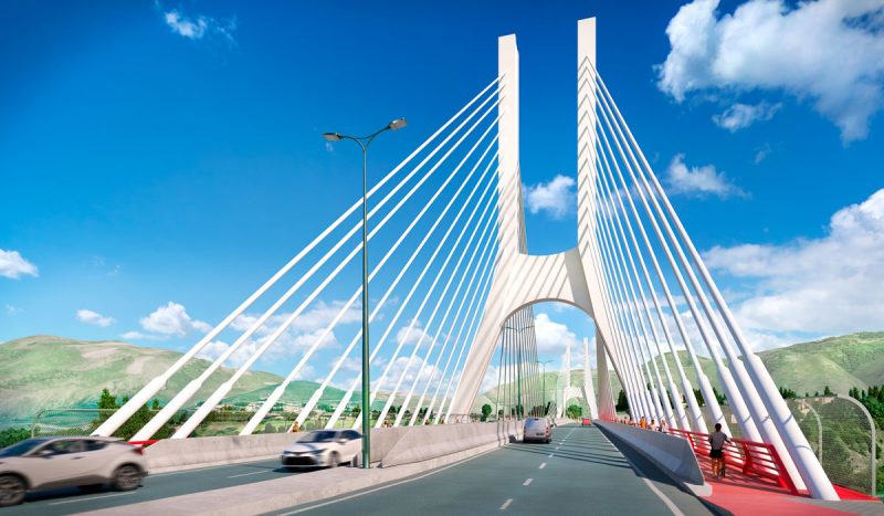
Stay Cable system
At the top of each pylon, the stay cables are anchored and tensioned. Each shaft has 13 levels, with a back-span cable balancing the corresponding main-span cable. Any imbalance in the loads is absorbed by a metal box girder, which is connected to the concrete shaft. The stay cables rest on beams, which transfer the load to the sides of the girder.
The front of the box girder is sealed with a metal plate, leaving an opening for the passage of the stay cables. This structure also serves as permanent formwork for the concrete.
For the deck, the stay cables are anchored at the edges and arranged in two groups, each consisting of 52 cables. These cables contain 31 to 73 strands, with each strand made up of seven wires. Due to the length of the stay cables, internal radial dampers (IRD) with three pistons are installed at the lower ends to control vibrations. The cables have triple corrosion protection (galvanisation, wax, and an inner sheath), together with an external protective sheath.
The construction process
The construction of the bridge will begin with the foundations of the pylons and abutments. It will then proceed with the pylon shafts and the deck of the back spans. The main span deck will be built cantilevered, supported by the cables connecting it to the pylon. The system formed by the side span, pylon, and cables will counterbalance the horizontal and vertical forces exerted by the cables supporting the central span as it extends towards the closure segment.
The general construction sequence is as follows:
- Construction of abutments and pylon foundations
- Pylon. The lower section is cast using ground-supported formwork. The upper section is cast using climbing formwork.
- Side spans are cast on temporary supports, while the main span is progressively extended using stay cables.
- Removal of falsework from the side spans.
- Closure of the deck and final finishes.