A historic bridge
The historic Pamban Island Bridge is an unelectrified single-track railway viaduct of approximately 2 km in length, connecting the island to the mainland of Tamil Nadu, in southeastern India. The bridge was in service for more than 100 years, until 2022, closed to traffic due to corrosion deterioration. There is a strong social demand for the railway service recovery, used by pilgrims visiting the island’s temples.
The construction of the historic bridge was carried out between 1911 and 1914. It has 145 spans of 12.2 m formed by steel beams, and a “Scherzer Rolling Bascule” type movable section with a 66.5 m of span, with by two leaves formed by a double steel girder each. This system, that can be defined as “back-rolling”, solves the movement by rolling over the circularly – shaped lower chord of each of the double girders. The operation is manually driven, using cranks.
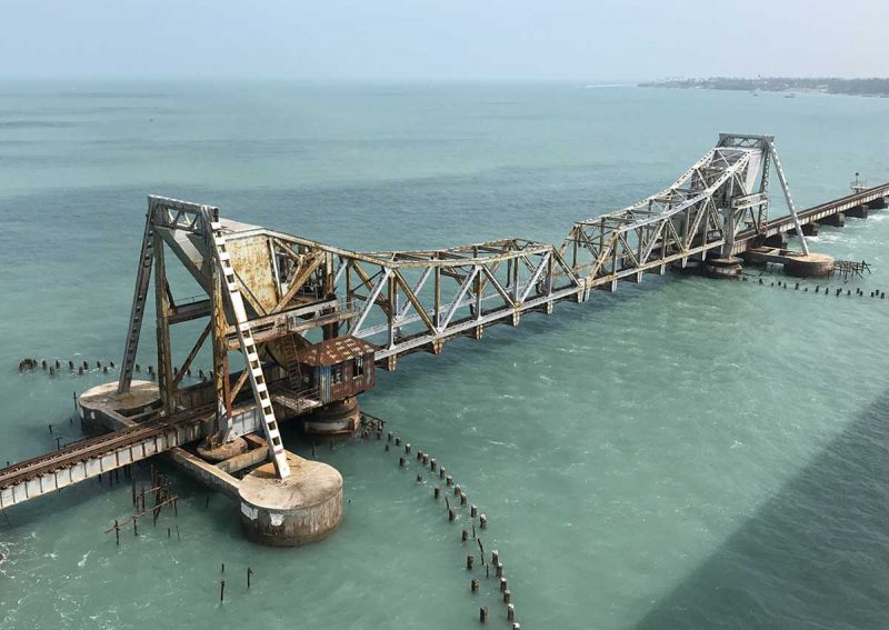 Existing “Scherzer Rolling Bascule” mobile bridge on Pamban Island
This century-old bridge is a national icon, was celebrated as a historic milestone at its inauguration, and is referred to as the first maritime bridge built in India. It is nicknamed “The Queen of Indian Bridges” and has become a tourist attraction in the south of the country.
In anticipation of the end of its service life, it was decided to build a new movable vertical lift bridge, automatized and motorized, ready for a future double railway track and the electrification of the line. The TYPSA-STUP-MC2 Joint Venture was awarded with the design and engineering construction services for the new bridge, promoted by RVNL, an Indian public company. The design stage began in January 2018 and ended by the spring of 2019, with the TYPSA Group companies being in charge of designing the movable bridge section, both structural and electromechanical components. The construction works were carried out between November 2019 and autumn 2024, by the Indian construction company RBL, suffering delays due to the restrictions of the COVID pandemic.
With the works completed, multiple tests and inspections have been carried out both on the circulation of railway compositions with speeds of up to 90 km/h, exceeding the planned operational speed, and on the manoeuvres of the movable bridge. The official inauguration of the bridge by the Indian Prime Minister is scheduled for early March 2025. The local press and social media are closely following the new bridge, which they refer to as “a marvel of modern engineering”.
Description of the bridge structure
After a previous study of solutions, a vertical lift movable deck solution was proposed. It follows the scheme widely named as “Tower drive vertical lift”, looking for a simple construction and maintenance system. It essentially consists of a set of sheaves, cables and counterweights that allow the deck to be raised and lowered by means of low-power electrical motors, which are located at the top of the towers, away from the most corrosive environment.
The bridge’s movable deck consists of a single span 75.7 m long and 11.3 m wide, composed of two Warren-type lateral steel girders with variable height, with a maximum of 9.9 m at the centre of the span. The total weight of the movable deck’s steel structure is 4240 kN, resulting in a total permanent load value of 5440 kN after including the dead load of the rails, sleepers, fixings and maintenance walkways.
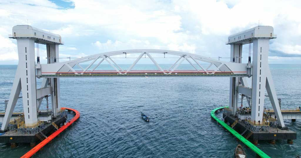
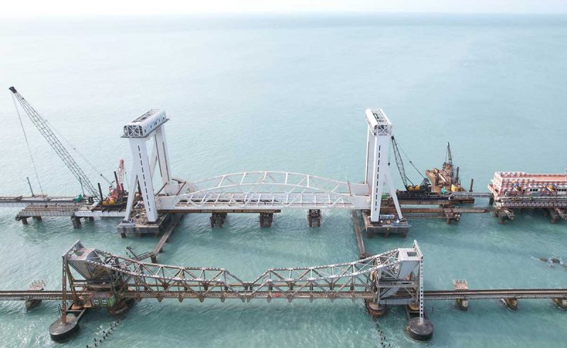 New Pamban Bridge at closed position with the ancient bridge it replaces
The structure of each of the towers, from which the movable span hangs, consists of two vertical shafts that transfer the vertical loads to the foundation, two dorsal inclined struts that collaborate with the shafts to cope with the horizontal actions, mainly wind and the earthquake loads, and an upper lintel that generates a frame system in the transverse direction together with the vertical shafts. The lintel also has the essential function of housing most of the electromechanical systems for the span’s movement and the control room.
On the other hand, the rails and guide channels for the movable deck and the counterweight are respectively arranged integrated into the shafts’ cross section. In addition, inside the shafts are located the stairs and the elevator for accessing the machinery and control rooms.
From the point of view of the durability of the structure, the bridge is located at one of the harshest marine corrosion environments in the world. A coating protective system with the highest efficiency, demonstrated in offshore applications, has been chosen; it is composed by a zinc thermal projection metalizing (TSZ) base layer, an epoxy sealant intermediate layer and a polysiloxane finishing layer. In addition, special care has been taken to design smooth and continuous surfaces, avoiding areas of water stagnation, or details that hinder the application and maintenance of the protection system. The coating’s durability is planned for 50 years before its theoretical need for renewal, provide that regular maintenance is given. Besides, the height of the deck over the sea level has been raised 5 m compared to its predecessor, to avoid the splashing zone and the most corrosive environment. The design service life of the bridge is 100 years.
The counterweights located at each of the towers have the function of theoretically balancing the weight of the movable span, so that the power of the motors is the minimum demanded by the inertial forces and the friction of the mechanisms. However, in practice, it is necessary to arrange counterweights that are lighter than the theoretical 100% balancing weight of the span, so that, under the action of permanent loads in the closed bridge position, a slight positive reaction is obtained on the supports of the deck, around 65 kN per bearing. Taking into account the above, the expected counterweights have a total theoretical weight of 2590 kN each.
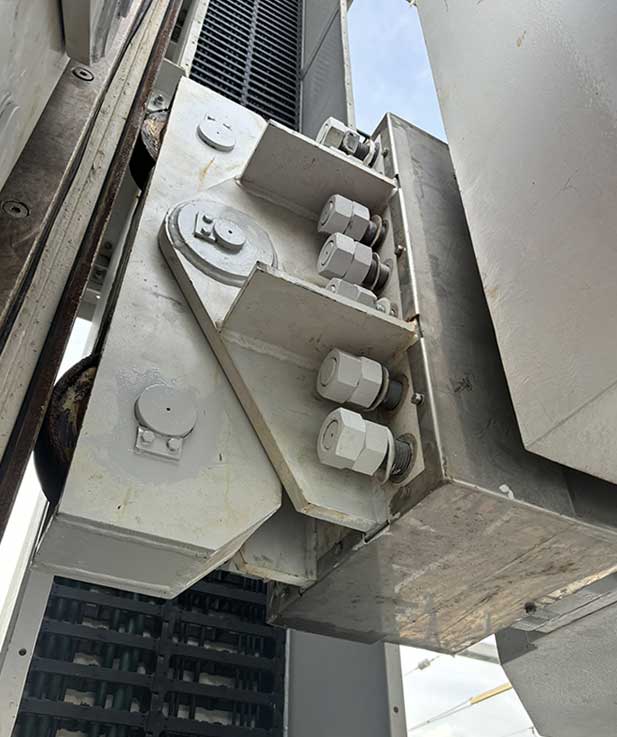
The proposed lifting system consists of four sets of six 46 mm diameter ropes, made of 1960 MPa grade galvanized steel, located at the four corners of the deck. The ropes have an adequate composition structure so that they behave flexibly and adequately against abrasion and bending fatigue. They are connected to high-strength bars at the counterweight edge, which are used for tensioning. At the deck’s side they are connected through tensioning turnbuckles, which allow the initial tension adjustment of the ropes during the loading process. The connecting pin bolts are instrumented for the monitoring of the ropes’ tension.
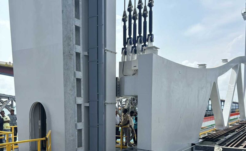 Connection of the ropes to the deck through turnbuckles
The diameter of the sheaves is set at 3 m, to limit issues such as excessive ropes’ abrasion and bending fatigue. They are made of 20MnCr5 cast steel in a single piece and subsequent machining of the ropes’ channel.
Electromechanical systems and automatization
Each of the sets of the electromechanical system, located within each tower, includes: a main electrical motor and a backup motor, gearboxes for adjusting the speed of rotation of the sheaves, hydraulic brakes and automatic lubrication units.
Each motor has 250 kW nominal power and is connected to the primary gearbox by means of a clutch, which allows the main motor or the backup motor to be engaged alternatively in the event of a breakdown or a scheduled maintenance. To reduce the rotational speed of the motor, 750 rpm, to the desired speed for the sheaves, 0.5 rpm, a gearbox system is used, consisting of a primary gearbox, with a power factor of 9.33, and two secondary boxes, with a power factor of 20.93. The output shafts connect a main pinion to the main gear ring, with a diameter of 3250 mm, with a diameter ratio of 7.5. In total, the resulting global power factor is 1465. Thus, the complete lifting maneuver of 17 m is carried out in less than 5 minutes, including the acceleration and deceleration ramps, with a maximum speed of 4.8 m/min.
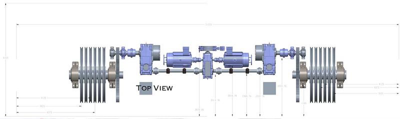 Schematic view of the mechanisms
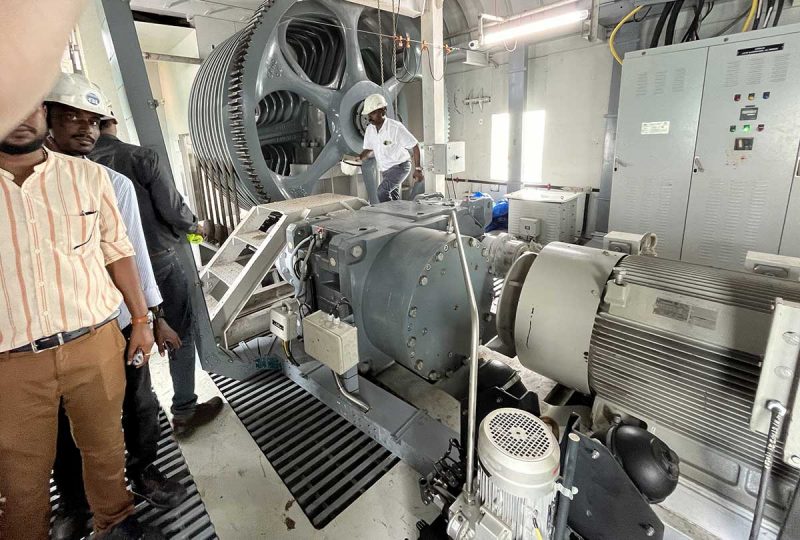 View of the secondary gearbox, main gear and sheaves. At the front, the motor. At the background, the electrical boards with the variable frequency drives
Variable frequency drives are provided to ensure smooth starting, and adequate acceleration and deceleration ramps. The system includes two braking systems: a motor brake, installed at the primary gearbox, which allows the operation’s control; and two emergency machinery brakes, installed at the secondary boxes, capable to stop the movement of the bridge in less than 10 seconds in any abnormal situation. Emergency brakes are negative action type, which means that they will brake the bridge in the event of a power supply failure: at rest, the brakes are activated.
The power supply is guaranteed by an 11 kV power line that reaches the designed electrical building, close to the bridge, from the mainland. It houses an 800 kVA transformer and a set of two diesel generators, each of 625 kVA, which can operate the bridge in the event of a power failure.
The bridge design includes, in addition to the mechanical and electrical drive systems, a SCADA system for automatized bridge control. The system manages a large set of monitoring signals for the electromechanical systems parameters, the position of the bridge using laser probes, stress measurement on the ropes and on the steel structure, anemometers, etc. It also integrates the control and signalling of railway and maritime traffic, in order to ensure maximum safety for users.
Unique elements of the movable bridge
Movable bridges require unique structural elements, not common in other bridges, that allow them to function correctly, some of which are described below.
Bearings
Complex tailor-made spherical bearings are designed, since they must simultaneously withstand the maximum vertical reaction (9300 kN), accommodate the longitudinal movements of the deck (125 mm), allow the deck rotation and, especially, allow the deck’s lifting, ensuring the correct alignment of all the components at the lowering manoeuvre.
The upper part of the bearing, responsible for the rotation of the span, is anchored to the steel deck, accompanying it in its movement. The lower part, anchored to the concrete pile cap, is responsible for the horizontal movement allowance; it has springs to ease the re-centring of the sliding component that is released when the bridge is lifted. The contact surface between the two parts has a conical shape, so that the lower part fits in place during the closing manoeuvre.
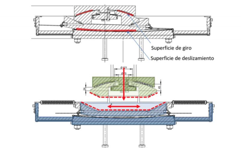 Schematic functionality of the bearings
 Bearings at the closed position and during lifting
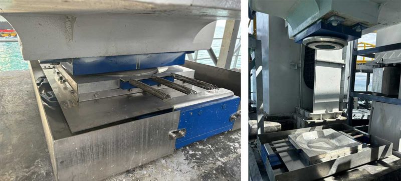
Centring devices
Since the spherical bearings cannot prevent the movement of the span, it is necessary to have elements that act both as fixed points for horizontal forces (wind, earthquake, braking and acceleration of railway traffic, among others) and as centring devices to ensure the correct positioning of the bridge and the tight alignment of the rails at the edges, with millimetric tolerance.
Stainless steel short poles are installed at each of the pile caps for these purposes. One of them exclusively blocks the transversal movement, while the other blocks the two orthogonal directions’ movement. Structural stoppers are placed at the deck, on which heavy-duty rollers are anchored to ease a smooth closing manoeuvre.
 Centering during lifting
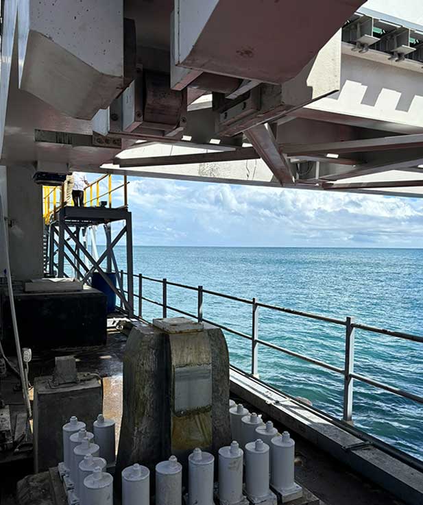
Locking devices
Due to the effect of the counterweight, the reaction on the bearings is very low; it is necessary to have a system that prevents the lifting of the span because of the wind and seismic actions. For this purpose, vertical locks are installed at each bearing, designed with stainless steel bars that are inserted into the lower chord of the deck, driven by a double-acting hydraulic cylinder.
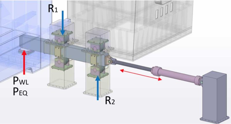 Resistance scheme of the locking devices
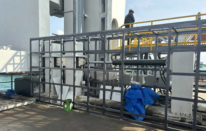 Deck’s locking device
A similar locking device scheme is provided for the counterweights, for maintenance operations or eventual replacement of ropes.
Guiding system
During the lifting and lowering operations, it is necessary to have transverse and longitudinal guiding systems for the deck, which must withstand wind or seismic loads happening during the manoeuvre. They also must compensate both the surface irregularities and the thermal movements of the span. Guiding systems are anchored to the deck are designed for this purpose, consisting of articulated bogies and a set of pre-compressed springs that ensure permanent contact between the guiding system and the towers’ corners.
 Transversal guide
In the same way, counterweight guides are designed, based on the same bogies with pre-compressed springs principle.